Magnetic Levitation
| Summary: |
Students learn about forces (gravity and magnetism)by investigating several configurations of a simple "magnetic levitation" system. | Materials:
Worksheet:
|
| Source: |
Windows to the Universe original activity created by Randy Russell. | |
| Grade level: |
4-8 (basic activity) or 7-12 (using measurement & prediction extensions) |
|
| Time: |
30 minutes | |
|
Student Learning Outcomes:
|
|
|
| Lesson format: |
Hands-on activity | |
| Standards Addressed: |
|
DIRECTIONS:
Part 1
- Place the end of the dowel rod into the hole in the block of wood to create a stand with the dowel mounted vertically.
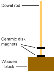
- Place two disc magnets on the dowel rod (with the rod through the holes in the middle of the magnets). Do the magnets stick together, or does the top one "levitate" above the bottom one? What can you say about which poles of your magnets are towards each other? If your magnets are stuck together, slide the top one off, flip it over, and put it back on. It should now "levitate" above the other magnet (see Figure 1).
- Describe the forces on the top magnet. (Hints: Is something pulling it down? What? Is something pushing it up?)
- Predict what will happen if you press the top magnet down onto the bottom magnet, then quickly release it. Then do it and describe what happens.
- Closely observe how far apart the two magnets are.
 |
 |
 |
Figure 1 |
Figure 2 |
Figure 3 |
Part 2
- Remove both magnets from the dowel rod post.
- Put two magnets together so they stick to each other, then slide them over the post and rest them on the base of the stand.
- Place a third magnet onto the post. Orient it so that it levitates above the other two (so it doesn't stick to them). See Figure 2.
- Compare the setup in Part 1 (Figure 1) with your current setup (Figure 2).
- Is the top magnet closer to, farther from, or the same distance away from the magnet below it as compared to the setup in Part 1? Why?
- What is pushing the top magnet up? What is pulling it down?
- Can two magnets work together to create a stronger magnetic force than one magnet would?
- Remove all three magnets from the post.
- Slip one magnet onto the post, resting on the wooden base.
- Put two magnets together so they stick to each other. Slide the two magnets onto the post. Orient them so they levitate above the bottom magnet (Figure 3).
- Compare this setup with the Figure 2 setup.
- Is the gap between the levitating magnet(s) and the magnet(s) on the base larger, smaller, or the same size as the gap in the Figure 2 setup? Why?
- How does the gap compare to the Figure 1 setup?
- What is pushing the top magnets up? What is pulling them down?
- Is the magnetic force that holds the top magnets up the same as, or different from, the magnetic force in the Figure 2 setup?
- "Weight" is the word we use to describe the force of gravity that pulls on some mass. Compare the mass that is levitated in your current setup with the mass that is levitated in the Figure 2 setup. Which mass is larger? How much gravity force, or weight, is there in each setup?
Part 3
- Remove all three magnets from the post.
- Slip a single magnet onto the post so that it rests on the base. Add a second magnet, oriented so it levitates, as shown in Figure 1.
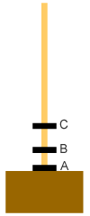
- Add a third magnet, oriented so it levitates above the second (Figure 4).
- How does the distance between the bottom two magnets (magnets "A" and "B" in Figure 4) compare with the distance between the two magnets in the first setup (Figure 1)?
- How does the distance between the bottom two magnets ("A" and "B") compare with the distance between the top two magnets ("B" and "C" in Figure 4)? What forces are acting on magnet B? magnet C?
- Is magnet A pushing or pulling on magnet C?
- Lift magnet C off the top of the post, but be careful to keep it oriented the same way. Lift magnet B off the post and set it aside. Replace magnet C on the post, keeping the same orientation that it had before. What happens? What can you say about the orientations of the North and South poles of each of magnets A, B, and C?
 |
 |
 |
Figure 1 |
Figure 4 |
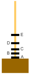
Figure 5 |
Part 4
- Add two more magnets to the three already on the post. Orient the two new magnets so each levitates above those below it, as shown in Figure 5.
- How does the distance between magnets A & B compare to the distance between magnets D & E? Explain the difference. What forces are acting on magnet E? on magnet B?
- Next, examine how well the magnets bounce, or "oscillate", with different setups.
- Build the two magnet setup shown in Figure 1. "Bounce" the magnet as you did in step 4 in Part 1. Bounce the magnet a few times, noting how high it bounces and how long the bouncing continues.
- Now set up three magnets as shown in Figure 4. Try bouncing the magnet stack. Note how high the top magnet bounces, and how long the bouncing continues.
- Set up five magnets as shown in Figure 5 and bounce the stack. Observe the bounce height of the top magnet and the duration of the bouncing.
Measurement & Prediction Extensions
You might want to add two extensions to this activity if working with older or more advanced students. One extension involves having students make predictions about results before trying each setup. A second extension involves having the students make measurements of the distances between the magnets.
- To add the prediction extension, have the students proceed as described above through the four parts of this activity. However, before constructing each setup, have the students predict the results, especially the relative spacing between the magnets. You may want to have them write down their predictions before they test them, possibly including an explanation of each prediction.
- If your students are familiar with vector force diagrams, you can have them draw diagrams indicating the forces on some or all of the magnets in each of the setups.
- To add measurement and quantitative aspects to this activity, have students measure the distances between magnets in each setup. This works especially well when combined with the prediction extension; have students predict the distances before trying each setup, then record their actual measurements and compare with predictions. Vector force diagrams can help in this analysis, and can help you as a teacher assess how well the students understand the configurations.
- You might want to have students weigh the magnets to determine their masses, then use that information as part of their quantitative analyses.
BACKGROUND INFORMATION:
Your students need to realize that magnets have two poles (North and South) to understand this activity. They need to know that like poles (N and N or S and S) repel each other, and that opposite poles (N and S) attract each other.
The poles on the disk magnets are on the flat sides. Image one of the disk magnets is a coin (with a hole in the middle!). Heads is North, tails is South (or vice versa - but the point is that the flat sides are the poles).
In Step 2 of Part 1 of the activity (see Figure 1), two like poles are facing each other, so the magnets repel each other. The magnetic force between the two magnets pushes the top magnet upward, preventing it from sliding down on top of the bottom magnet. The force of gravity pulls down on the top magnet, preventing it from flying up off the top of the post. So in Step 3, the two forces at play are gravity (pulling down) and magnetism (pushing up). The two forces are at equilibrium (they "balance out" each other), causing the top magnet to levitate a few centimeters above the bottom magnet.
In Step 4, students will discover that the top magnet undergoes a damped oscillation (it bounces up and down for a while, but eventually stops) when they press down and release the magnet. Oscillations are very common phenomena in both natural and human-made systems. This is a damped oscillation because it doesn't just go on forever; friction between the magnet and the post stops it pretty quickly. Ask your students to mentions systems they are familiar with that behave similarly; a good example is the suspension of a car when it hits a bump.
In Step 4 of Part 3 (Figure 4), the middle magnet (B) should be closer to the bottom magnet (A) than it was in the case shown in Figure 1. The weight of the top magnet (C) is pushing down on the middle magnet (B). The magnetic repulsion that keeps A and B apart was just holding up the weight of one magnet in Figure 1; it is holding up the weight of two in Figure 4; so magnet B "rides" lower. Note that this is comparable to the case in Figure 3; the position of the middle magnet is a consequence of having the weight of two magnets pressing down on it. This is more obvious in Figure 3, where the top two magnets are touching, than in Figure 4, where the force of the weight of the top magnet is not pressing down on the middle magnet via direct contact; instead, the weight (force) of the top magnet is "pressing" down on middle magnet via the magnetic repulsion force between the two magnets.
When the students bounce the magnets in the Figure 4 setup, the damped oscillatory motion will be similar to the Figure 1 case, though a little more complex. The "bouncing" probably won't last a noticeably longer or shorter time. If anything, the bouncing should stop more quickly in the Figure 4 setup.
The forces in the Figure 4 case are quite interesting. If we assume that the top side of magnet A is a North, then the bottom side of B is a North as well (so the two repel). That means the top of B is a South, and thus the bottom of C is also South. So A and C are actually pulling on each other a little bit. The North top of A "sees" the South bottom of C and is attracted to it (even with B in between). The force is quite small since the magnets are a ways apart. However, the distance from A to C is a little less because of this slight effect. The change is almost certainly not noticeable to the eye, and probably cannot be measured in this simple setup. It is a good puzzle to test your brighter students with, however. In Step 7 of Part 3 this relationship plays out when we remove the middle magnet (B) and A and C stick together.
In Step 2 of Part 4, the magnets should end up with a spacing something like that shown in Figure 5. The bottom magnets (A and B) should be closest together; the top two (D and E) furthest apart. Magnet B "feels" its own weight plus the weight of the three magnets above it pushing down; it only has the force of one magnet (A) pushing up on it. Gravity wins out, wit a score of four to one. Magnet C "feels" the downward weight of three magnets (itself plus D and E), and the upward repulsive magnetic force from the magnet directly below it (B). So the score is three down to one up, and C "floats" a little higher above B than B does above A. And so on up the stack. There are other minor attractive magnetic forces at play, as described above for the case of Figure 4; but they are much smaller effects and not readily noticeable (if at all).
What happens when you "bounce" the five-magnet system? Hopefully, the students should notice that the bouncing stops (damps out) more quickly than in the figure 1 case. More complex systems (with more "degrees of freedom") tend to be harder to keep oscillating that simple systems with fewer parts. There are exceptions, but in general if you "wiggle" a complex structure it will tend to damp out pretty quickly, whereas a simple structure might continue oscillating for a longer time.
Figures 2 & 3 illustrate the setups for Part 2. In each case we are combining two or more magnets to increase the magnetic force. When we put two on the bottom and one on top (Step 3, Figure 2), the top magnet "floats" higher (than when just one is on the bottom). The weight of the single top magnet is countered by a greater upward force from two magnets pushing upward together from below. In Step 7 (Figure 3), the magnetic force pushing up is the same as in Figure 2, but the weight on the top is doubled, so the gap between is smaller than in Figure 2.
RELATED SECTIONS OF THE WINDOWS TO THE UNIVERSE WEBSITE:
References & Background Information:


